
cdaringe
learnings, nerdisms, bicycles
about
rad
freshawair
up'n'up
pl selector
github diary
dvd.js.org
standup
donut
cowtown
truth.lol
fish.js.org
factorio-type-kit☠
red-or-green☠
senor-salsa☠
On building a keyboard - forestboard
September 10, 2026
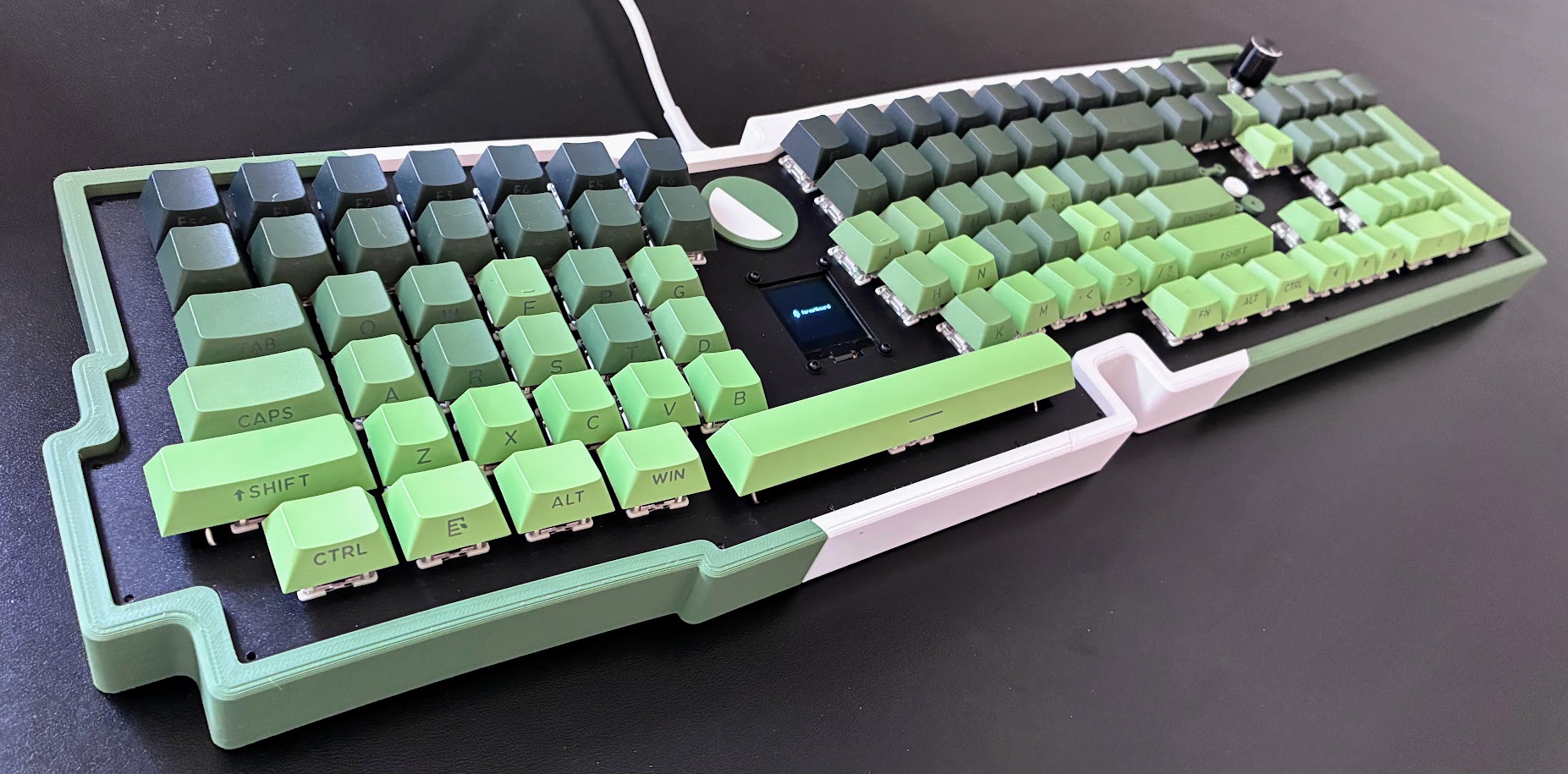
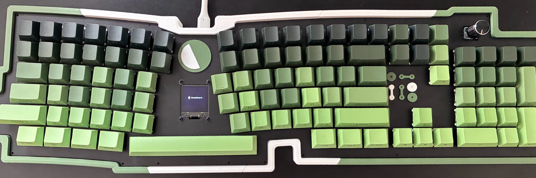
I built a keyboard. I designed the full PCB (including layout), sheet metal plate, case, and firmware.
The major takeaways I have to share are:
- It's surprisingly easy to just do the whole process using commodity tools & software
- It's surprisingly affordable
- It's fun!
- It's a lot of work if you're doing a full sized board and a net-new design.
Why
There are seemingly infinite keyboards on the market. Why build one? Just buy! It will be cheaper and faster!
It all started with Dyson Sphere Program. It was a relaxing Saturday morning, and I thought, "Let's get some DSP in, now that all games just work™ on Linux!" I booted it up and... uh oh. My Colemak keyboard layout strikes again. I forgot to switch to QWERTY before launching the game!
This is a common problem with games. Us non-QWERTY users frequently encounter software that eagerly binds controls to logical keys rather than physical key positions. This is a fatal accessibility mistake. When a game maps WASD keys into up, left, down, and right motion, Colemak users instead get up, left, nothing, and down motion. It's confusing and unusable.
Usually, the fix is to exit the software, switch keyboard layouts, and try again. On this day, that simply didn't work. Somewhere behind the Steam+Proton+game boundary, the controls remained permanently bound to the wrong keys. I tried all sorts of crazy things, but ultimately the fix was to reinstall the game.
Never again. Alright, so just use a keyboard that supports custom layers! Easy! My old ErgoDox supported that, as do many of the custom flashable boards. It'll sling a different scan code to the host OS!
The more I thought about what I wanted, the more nuanced my requirements became:
- Fixed, ergonomic split. I didn't want the wandering independent halves of boards like my old ErgoDox. I love Microsoft's fixed ergo boards. I've used them regularly since I was a kid! A wide, split layout also helps keep my shoulders neutral.
- Key layers. If I could remap the board with the touch of a button, a game's sticky, eager key bindings would no longer matter.
- Steeze. I need something completely rad. I'm not deep into keyboard culture or klacky switches. I just want to look at my keyboard and think, "This is awesome."
- Minimal weirdness. I want standard WASD, modifier keys, spacebar, arrow keys, and a numpad. Writing, programming, gaming, numerics/Excel--something always feels lacking without these standard, unmeddled features. I want a true general-purpose keyboard, so I can't get too weird with it.
- Full size. Small keyboards are cute, but this is my primary interface to all compute. I just don't get the deal with people and tiny keyboards. Deskspace isn't a problem--it's abundant! I want MAX(fn(efficiency, effectiveness)). As a generalist, I type numbers all the time, and nothing beats ripping through them on a numpad. It's frequently skipped on fancy keyboards. I don't get it. I guess I'm the oddball.
There is not a board on the market that fits all of those requirements. Some Kinesis knock-offs come close (maybe), but they also come with really wild physical key orientations. That violates "minimal weirdness," so they are all out as options.
Ugh, am I really going to build a keyboard? What a loser! Fine. Just do it.
Design
Layout
The super cool KLE layout editor is where I started. I was immediately defeated by the fact that it only operates on a rectilinear grid. That's right--rectilinear. Go to hell Doug, it's a real word! I want a split board with contours! The KLE can represent rotated keys, but there aren't nice editing mechanisms to get them.
No worries, I'll just update that software deeply to add Bézier curve support!
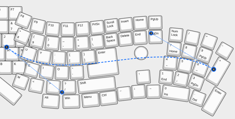
See? Done! With a bit of measuring and math, I was able to use the fullsize keyboard preset, mutate it via curves, and roughly approximate the Microsoft Ergonomic Layout. It's not perfect, and it took forever to really dial in precise locations that I was content with. I also updated the tool to replay mutations versus just do singular in-place edits, enabling me to roll back my edits, make micro-adjustments to curvature, then re-apply all of my following edits. This mirrors what 3D CAD programs do and saved me a ton of time. It took about 12 layout variants before I settled on a layout. I pinged the author of this amazing web tool and have some PRs staged if they are interested in merging these capabilities. It's a ton of changed code for an admittedly niche feature, so I'm not pressing it. It is available in my fork!
What makes this tool extremely compelling is:
- It exports JSON definitions of geometry, key styles, stabilizers, and even the EC11 rotary encoder. So much complexity and thinking, just handled. And it works great, no tweaking/tuning necessary!
- It exports basic kicad templates! Specifically, the worker backing the website provides to me a KiCad layout with all of the PCB switch footprints set, and the diodes set! Amazing! So I'd just have to route all of the traces, add mounting for my MCU, add anything I'd need for my screen, do the cutouts, and some copper layer malarkey. These aren't all easy tasks, but not too hard!
MCU Selection
MCU selection was difficult. The common wiring paradigm assumes a column/row grid. I have 100+ keys. Let's pretend it's exactly 100 for simplicity sake. If my keyboard was a perfect square, I'd need 10 rows and 10 columns--which is 20 GPIO pins. Yikes! My keyboard is not square at all. The naive wiring for this board is 6 rows by 21 columns--27 GPIO pins! If I want a rotary encoder/knob and a screen, that's another 7-ish pins? I'm running out of pins fast! Perhaps I can just use a board with a boatload of pins? The answer is... kind of? Boards with 30+ pins tend to be large and tend to have physically larger SoCs. Most importantly, bigger MCU boards aren't well tested or first-class with popular keyboard firmwares like QMK or ZMK. I checked the MCU compatibility pages, and somewhat quickly narrowed my selection set down to the STM32 family. Whilst I surely could have used an alternative, this seemed like avoidable complexity. I wanted a board with a small footprint so it fits into a compact case, which means I needed to keep my pin count low.
I read around, and there's a well known Duplex wiring scheme. I had already been thinking along these lines ("What if I folded my board in half, so that I have one column span two rows, on opposite sides of the board?"). Sure enough, that's the exact prescription:
Duplex wiring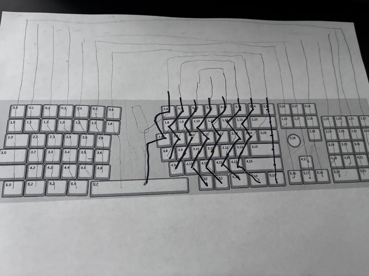
I sketched it out, and consequently cut my column pin count in half, but also doubled my rows, as now each row only traverses half-width. My crappy drawing shows the U/rainbow shape of the column traces. My scheme is now (2x6) rows x 11 columns. Nearly square! Thus, my I/O is nearly optimized--23 pins for actual keys. For the screen I wanted, I'd need 5 pins for SPI, then a couple for the encoder. In total, 31 GPIO pins were required. I spent an irresponsibly long time trying to find the right board for this, but settled on the WeAct STM32FW boards. Upside: compact! Downsides: shared rows for pins meant I couldn't use all of my breadboards for debugging, and there's plenty of GOTCHAs with some pins being USB allocated, microSD allocated, etc. These also had enough mem on them to load a bunch of screen animation data, which I thought may be non-trivially expensive (from a mem volume perspective).
Electrical
Huge shoutout to scottokeebs for doing an extremely targeted kicad tutorial for keyboards on YouTube. I'm a mechanical CAD power user, so getting weird with electrical CAD wasn't so scary.
On my first design, I had the following macro PCB goals:
- diodes on the bottom of the board
- MCU on the top
- OLED screen on the top
Get to work!
Drawing up the schematic Final Kicad traces, after all of the bugfixes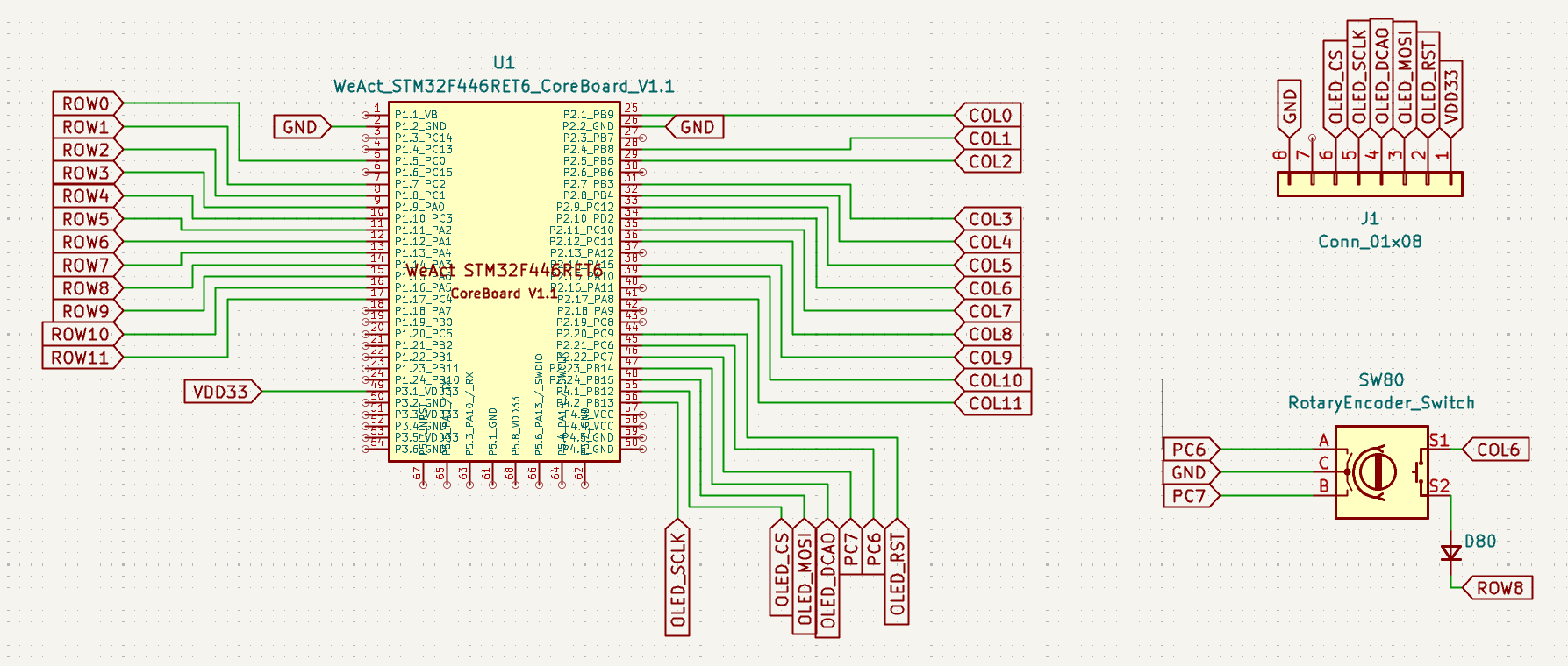
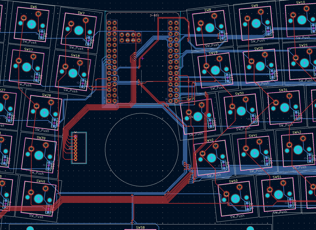
Kicad is an art. Moving traces around and grouping them neatly is surprisingly fun. I tried an autorouter, but it ran for over 30 minutes without producing a result, so I routed the board by hand.
The painful part came later. Kicad didn't gracefully reroute existing traces when I moved a fully connected footprint, so every major component change meant substantial rework.
And I ended up moving things a lot! Remember where I said I was going to put the board on TOP of the PCB? Huge mistake. You need to press the onboard MCU board buttons to initiate a flash. With a solid sheet metal plate above, there's no opportunity to do so. Thus, one big move was moving the MCU board to the back of the PCB. This meant all of my top of board tracing was largely useless! I rewired all of that up, only to find later that footprint also needed to be flipped about the X axis, because I had the USB-C port pointing into the inside of the board. Rookie move! I will have now re-routed traces for a third time! Next up, the screen shouldn't have been mounted to the PCB, but to the sheet metal plate, for obvious reasons. This wasn't so bad, but caused me to investigate low profile right angle connectors. I found some nice 7 & 8 SMT connectors for dirt cheap on digikey, and got the footprint loaded up. As you'll see later, by using a connector, I can gracefully position the screen onto the plate with slack in the wiring, which also unlocks some amount of serviceability of the screen. Easy!
One of the huge wins that I didn't mention earlier was getting footprints for all of the components in kicad. Kicad stores data primarily in (s-expressions), which looks pretty LISPy! For a few things I was investigating--the OLED screen, the connector I found on digikey, and the WeAct MCU board--not all had kicad footprints readily available. However, because of that extremely easy to parse/read/generate format, GPT was able to parse out some other specifications (STEP files, images, etc) and build me perfect kicad footprints. It was absolutely amazing to go from "how will i set up wiring between these two PCBs" to "I can bridge these two PCBs easily" in minutes!
Lastly, if you haven't done circuit design in CAD before, KiCad's Design Rules Checker is amazing. It flags clearance violations, unconnected nets, and mismatches between the PCB and schematic—even guiding you as you route traces. It can't prove that your circuit is correct, but it catches an enormous class of easy-to-miss mistakes.
Kicad 3D preview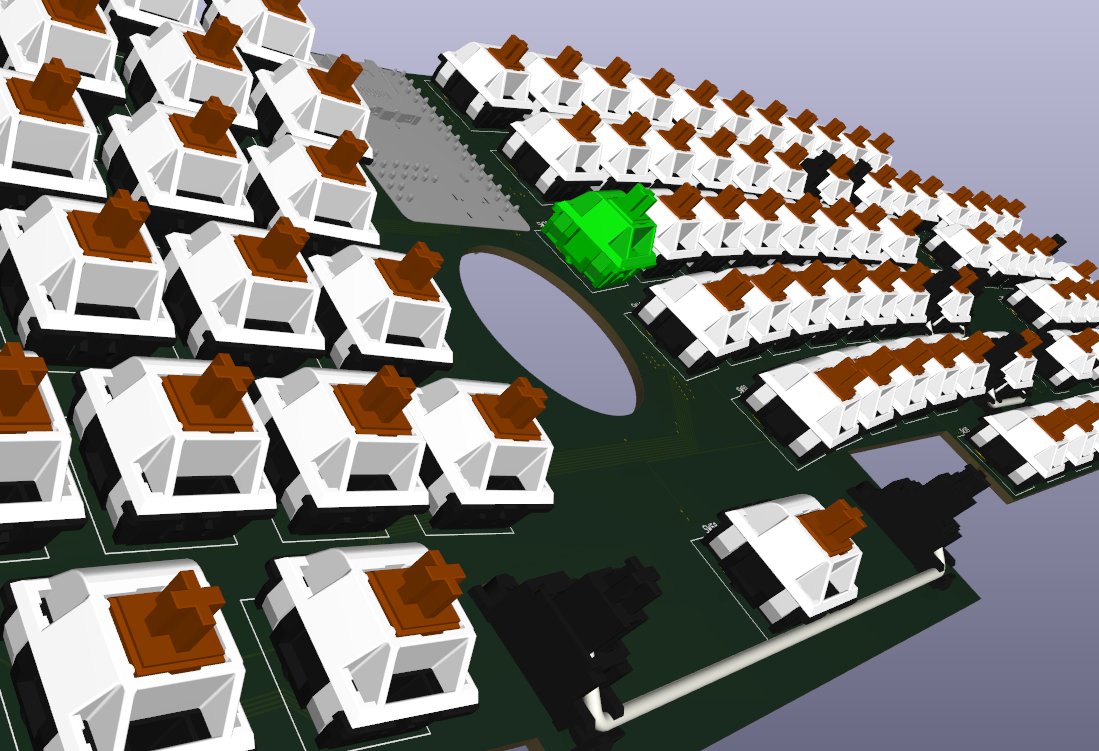
Mechanical Design
Case design & plate design should have been the easiest, and possibly the most fun. I've built hundreds of mechanical designs! However, there are dragons here. Why? Well, if you constantly change your PCB design, you need to constantly change your case design! That's not the software's fault, I suppose 😅. During the mechanical design phase in OnShape, I really started to physically engage with my design. I kept nit-picking little aspects of it, and redoing everything. "These keys are too close", "I don't like that angle", "this could be positioned differently to look cooler". I was forced to iterate a few times as well because the PCB vendor and the sheet metal vendor had additional constraints that I was violating, which sent me back to different design checkpoints. These are all quite painful, for the following reason:
When a kicad model is exported, there is not a workflow that allows updates to the same logical model in OnShape!
Huh?
My whole case and sheet metal are designed around the PCB. But when the PCB changed, I would have to fully delete it, and replace it with a new one. In most CAD softwares, sketches and features are designed around references, and the PCB hosted my primary references! Just deleting it could imply that I'd have to restart from zero. Eventually, I minimized my references to the PCB, and picked strategic geometry to base my design on. When I would delete my model in OnShape and swap it, I wouldn't have to do a ton of work.
This worked well when my case was rectangular:
Original, phase 1 rectangular case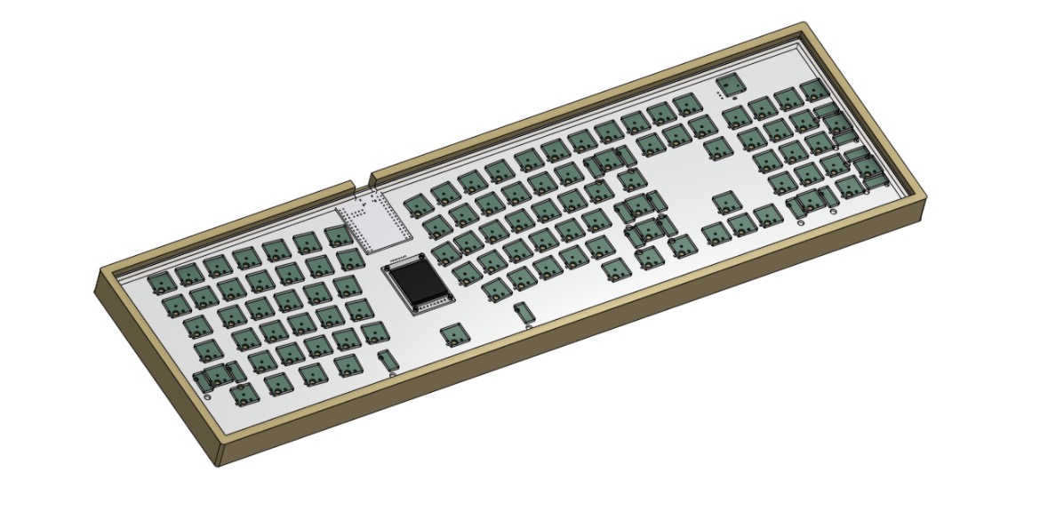
However, the more time I spent online seeing other folks building interesting keyboards, I realized, 🥁 rectangular is for squares 🥁! It would be fun to do something interesting for the aforementioned "steeze" requirement. Eventually, I landed on molding the case more to the intrinsic outline of the PCB:
Final case design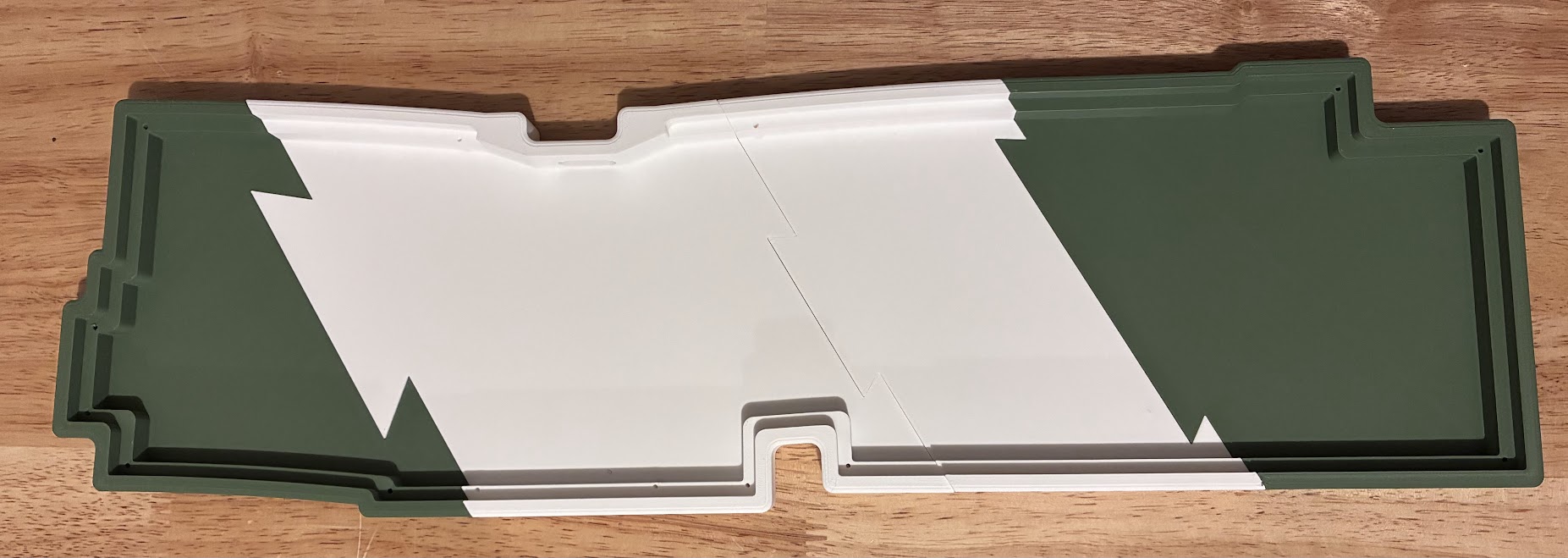
This got painful fast. Every time I replaced the PCB model in OnShape, that complex outline forced me to rebuild a bunch of non-trivial features. I eventually got the iteration loop down to under 15 minutes, but it took a while.
I'm going to skip over most of the mechanical design, but one detail came out particularly nice. The case has a shelf for the sheet metal plate to rest on. I added counterbores to the bottom of the case, through-holes up to the shelf, and matching threads in the sheet metal.
Now I can secure the plate to the case with a handful of screws. They're sized just right: they engage the full 2mm plate and end up flush with the bottom of the case 😙🤌. You can see the through-holes in the image above.
After I designed the case, I 3D printed a few test versions, and also 3D printed a partial test plate to ensure everything fit well before ordering.
Everything is swell with plate geometry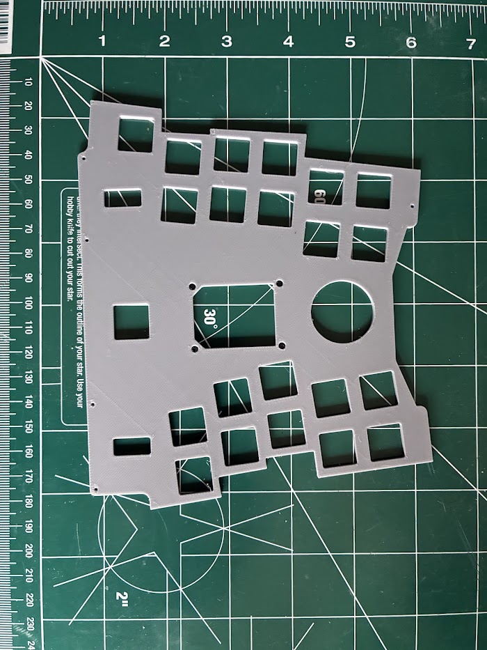
Order Up!

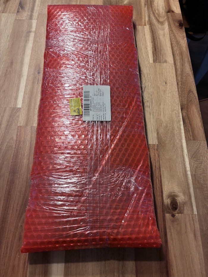
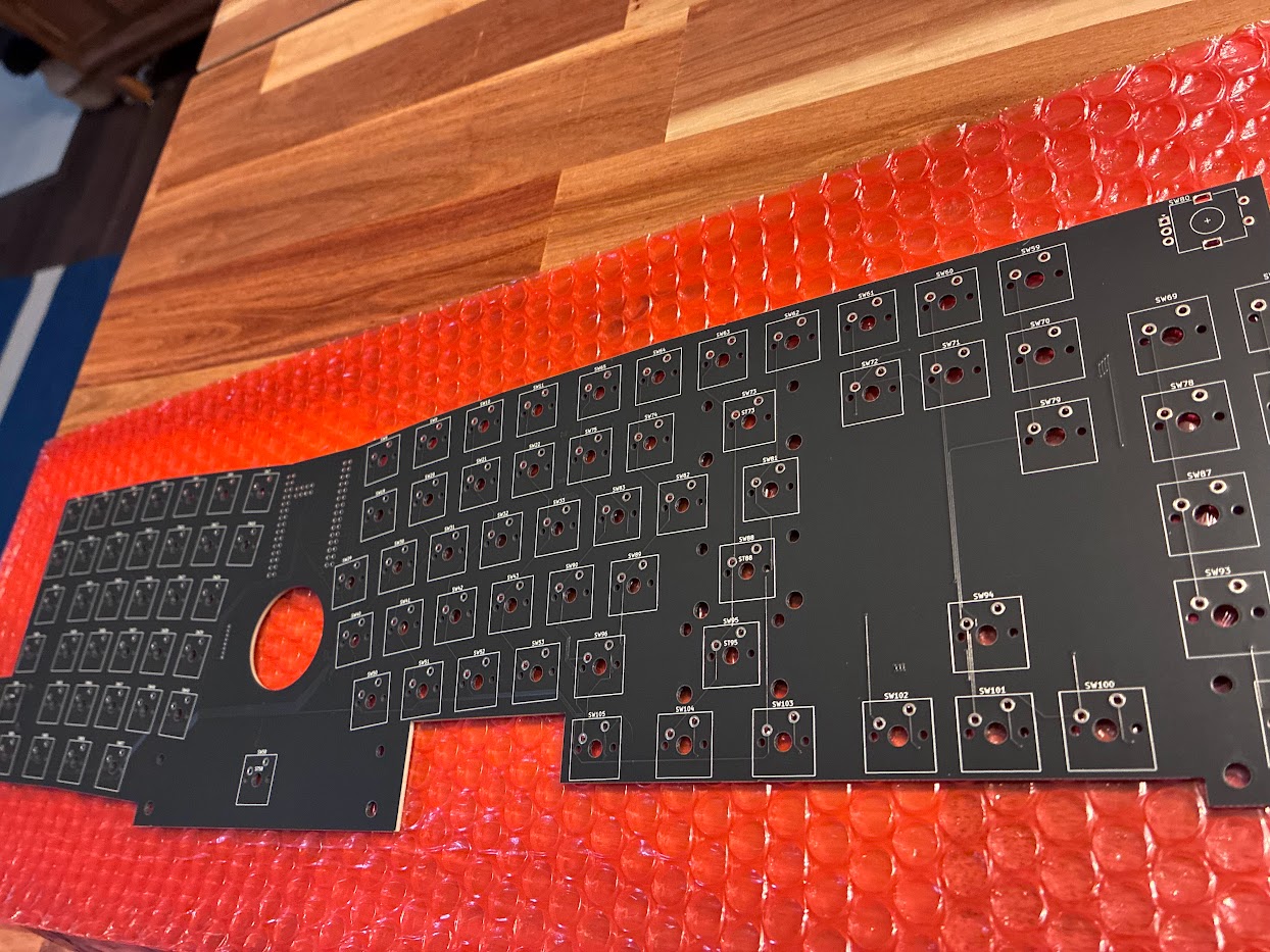
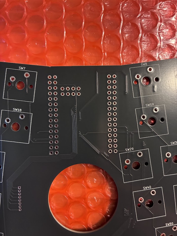
I am quite happy with the PCBs. The sheet metal also looks great, and you'll see that shortly.
Assembly
I have a bunch of video of all of this, but am sparse in photos. Here's the order of operations:
- Solder the screen connector to the PCB
- Solder the pins to the MCU board
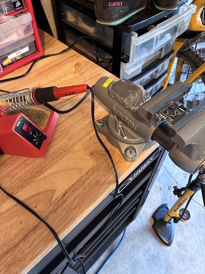
- Solder the MCU board to the keyboard PCB.


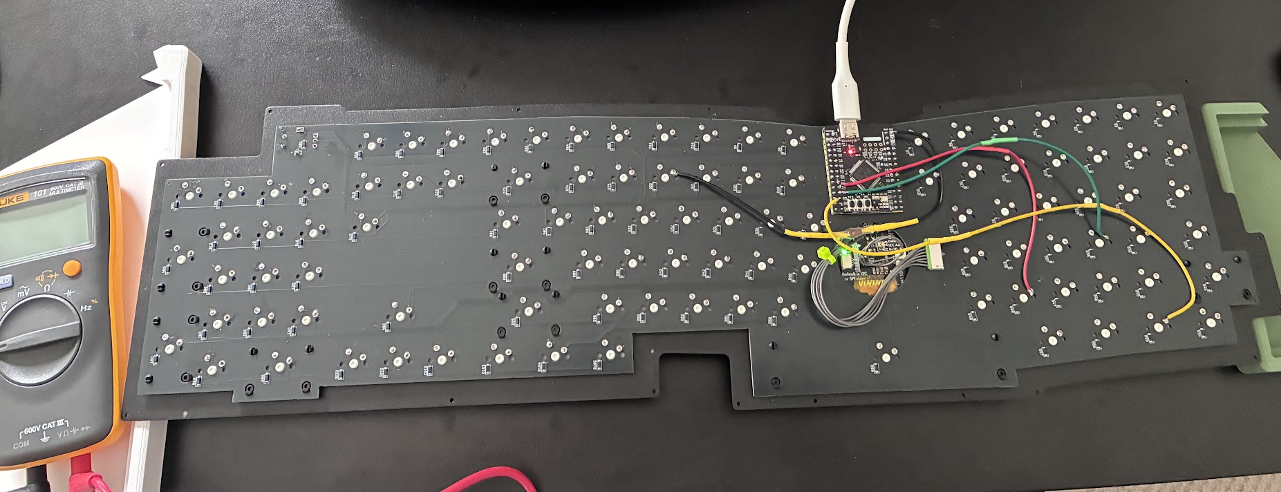
- Solder all the wires to the screen and connectors.
- Do some firmware pre-checks before assembling any further! Does that screen work?
- Mate the sheet metal and PCB. Solderfest! Solder on one drillion keys!
- Learn that you're incompetent and have terrible craftsmanship. Start using flux, learn from your mistakes, and compensate for your bad electrical handiwork.
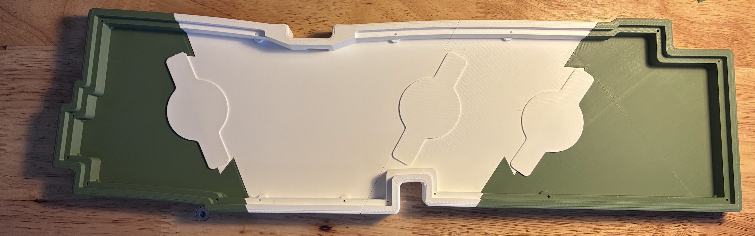
- Reinforce the case seams. The case was too big to print as one part, so I joined the pieces with dovetails. Those provide plenty of lateral tensile strength, but the seams can still move slightly when the keyboard is picked up or placed on an uneven surface.
- Bolt it all together, and slap the keys on:
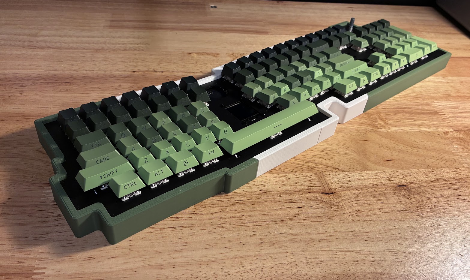
Firmware
The firmware might be my favorite part. It has interactive menus for configuring layers, screen behavior, animations, and more. Some of the screen features are gimmicks, but it does show useful statuses like the active layout, Num Lock, and Scroll Lock. The animations are fun, and update in response to your typing. There are even little celebration easter eggs when you surpass #count-keypress milestones :).
Conclusion
This keyboard was a ton of work. I probably shouldn't have done it, but it was fun. It set me back maybe 300 bucks, 100 of which was just tariffs and shipping. The most amazing component, the microcontroller board, was the cheapest component of them all, proving that the world is in fact upside down and terribly broken. Nonetheless the board is great to type on and genuinely unique. I have a few extra PCBs and one extra sheet metal cutout if you want to give it a go! I do have one or two minor critiques about the board itself now that I've been using it as a daily driver for a few days I had a hard time compensating fir the the y pos of the DEL and END key row, and think the comma key should maybe be 1mm or 2mm left relative to the row above. It seems to not be much of an issue now after using it for a bit, but the adjustment wasn't right away.
Thanks for reading!
Appendix
- firmware/github: https://github.com/cdaringe/forestboard